What You Need to Know Crosstalk
What You Need to Know Crosstalk for Implementing 10G Copper Solutions inside the Data Center
The industry has been predicting the growth of 10GBASE-T for years, and it’s finally happening. More networks are planning 10G migrations. Why? Due to demand from more advanced devices, users and applications. But new concerns come into play with this Ethernet standard. Crosstalk is a complicated subject to grasp, especially where the “Near” and “Far” ends are. In reality both end of the cable are both! They are only reference points to demonstrate where the signal is originating from for the purpose of the test…
The first diagram in this article shows exactly what happens, and how the “concept” of what is the Near and Far ends depending on which end the signal originates from. The diagram show a cable that is tested from either end and where the two ends are and where the NEXT and FEXT signals are in relation to the originating signal. When a signal legitimately travels down a pair of wires in a cable the signal emerges from the other end as it is supposed to, but the field that the signal creates around that pair “bleeds” over to the other pair in the test. The crosstalk creates a certain voltage in that wire that will emerge out of both ends, the near end and the far end. The following sections describe the different types of crosstalk and what the measurements mean.
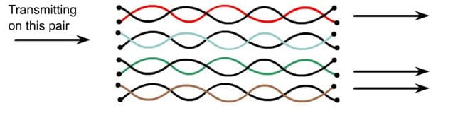
Near End Cross Talk (NEXT)
The technical definition is “Interference between two pairs in a cable, this is measured at the same end of the cable as the “interfering transmitter”. What this really means is that one pair can interfere with another pair at the end that is doing the transmitting at the time. In reality the transmitting cable will interfere all the way down the cable to the other end, but the interference will be the greatest at the end where the interfering signal is transmitted from, called the “Near” end.
As an example, a cable can be plugged into a network switch and that switch is sending data (sending an electrical signal), that electrical signal will travel down the transmit pair interfering with the other pairs in the cable at the connector. That is where the NEXT measurement is taken, it is one of the most important measurements when testing a cable (except for Power Sum NEXT), it is a fairly conclusive test for the actual manufacturing quality of the cable itself or whether the cable itself is damaged. One of the causes of NEXT is the way that the pairs are inserted into the connector itself, if the individual pairs are not twisted right up to where they enter the connector then there is a potential for crosstalk issues, commonly found with homemade cables.It’s hard to make cables correctly and the temptation is to untwist the pairs more than they should be to make the connector fit easily, but this will introduce a potentially unacceptable amount of NEXT interference.
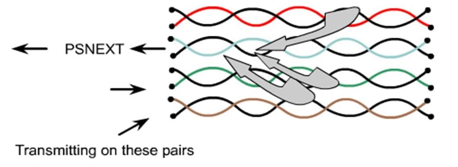
Power Sum Near End Cross Talk (PS-NEXT)
This is the same as NEXT, but is a calculation of the sum of unwanted signals from all the other pairs (in every combination) in the cable that affect the “victim” pair. Standards such as 10BASE-T and 100BASE-T only use two pairs in a cable, but the 1000BASE-t standard uses all four pairs in a network cable, which is where the Power Sum figure may be more relevant.
A cable that passes the PS-NEXT test should deliver superior performance for Gigabit and ten Gigabit networking deployments or any other network protocol that uses simultaneous parallel transmission. Using the PS-NEXT test cables can be “graded” rather than just being given a Pass or a Fail score.Cable grading is measured, in decibels, at a variety of frequencies that fall within the operating bandwidth of the that cable. There are 7 grade levels each one of which is 3db wide, the higher the grade the better the performance of the cable. The 3db measurement is in the NEXT/PS-NEXT margin at 100Mhz and a signal power difference of 2X.
Far End Cross Talk (FEXT)
As the name suggests it’s the same measurement as above (measuring the effect on one pair to another) but a the other end of the cable from the transmitting device. The effect is less than the near end measurement as it is measured at the far end of the cable.
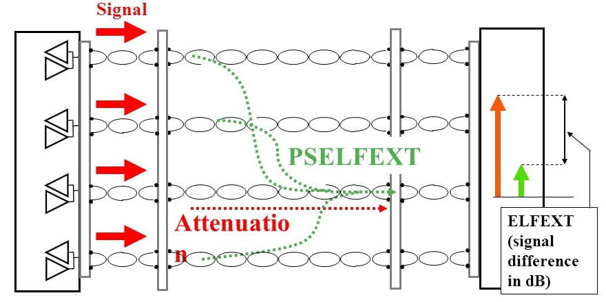
Power Sum Equal-Level Far End Crosstalk (PS-ELFEXT)
This measures the sum of the unwanted signals from pairs on the far end onto a pair on the near end.
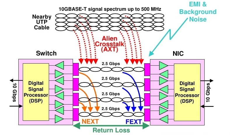
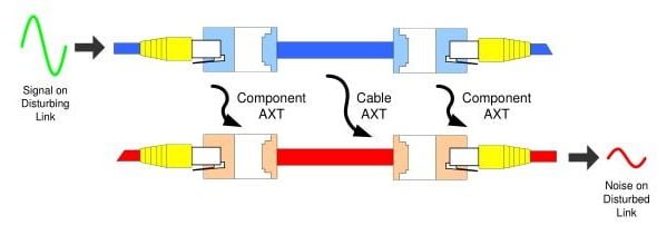
What is Alien Crosstalk?
Alien crosstalk is a combination of alien near-end crosstalk (NEXT) and alien far-end crosstalk (FEXT); the noise source originates from a common mode signal that is converted onto the differential mode signal through some type unbalance on cable and components.
Why is Alien Crosstalk Bad for Today’s Applications?
In high-speed, high-bandwidth applications – used today to accommodate more users and more devices – alien crosstalk can cause many problems. In a cable bundle, it’s possible that cable pairs in one cable pick up interference from pairs of another cable. The digital signal processors (DSPs) used in 10GBASE-T architectures can’t remove unpredictable exterior noise. Noise sensitivity increases at higher frequencies, such as 500 MHz, which is the highest frequency of Category 6A cabling. This interference isn’t just a nuisance; it has the potential to shut your entire network down – which leads to unplanned downtime, financial losses, a productivity nosedive and unhappy users.
What Causes Alien Crosstalk?
Alien crosstalk originates from a common mode signal that is converted onto the differential mode signal through some type of unbalance on the cable and components. Category 6A cabling and components are designed and tested to reduce alien crosstalk to a level low enough that it does not interfere with the differential mode signal.
Make sure all components are Category 6A. This is especially important to note for patch cords. When high-quality, Category 6 cable is tested, it may pass Category 6A patch cord requirements because only near-end crosstalk and return loss are measured. When these patch cords are bundled and placed in a Category 6A channel, however, the channel fails alien crosstalk requirements. Why? Because Category 6 cable isn’t designed to handle high data-speed requirements.
What Do Standards Say About Alien Crosstalk?
Alien crosstalk reduces cabling’s operational bandwidth due to increased channel noise levels; as a result, ANSI/TIA standards state that Category 6A cabling best meets the demands of 10G. (According to current standards, Class E and Category 6 cabling aren’t recommended for new 10GBASE-T installations over 37m.)
Here are a few reasons why Category 6A is the best choice:
- Achieving 10GBASE-T over copper requires 500 MHz bandwidth and full duplex transmission, which Category 6A provides
- It must follow stringent ISO/IEC and ANSI/TIA transmission-parameter regulations
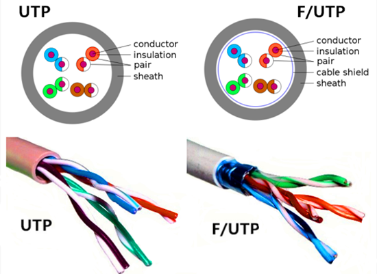
- It uses specially designed jackets and cross-webs that physically separate internal twisted pairs from external twisted pairs, ensuring low alien crosstalk
- It provides a guaranteed alien crosstalk margin above minimum TIA-568-C.2 requirements
- Category 6A specifications allow compliant cabling for 10GBASE-T transmission